
We have been battling with a cold lounge for a few months now. The adversary is the French, or to be precise the French doors which have managed to chill the lounge to a level where rugs on knees are required.
It has been a battle worthy of the Napoleonic wars: a massive build up of weapons and intelligence, thrust and counter thrust, and some false dawns. Whilst my wife and I have yet to score a decisive victory over our draughty French doors, we are moving into the final stages of the fight and appear to have the upper hand. It seems to be a good time to document our struggles for the benefit of posterity. Names and certain details have been withheld to protect both the innocent and the guilty.
The Battleground
We moved into our new home in mid-February 2015. With a house built with high levels of insulation and air tightness the last thing we expected was to be cold.
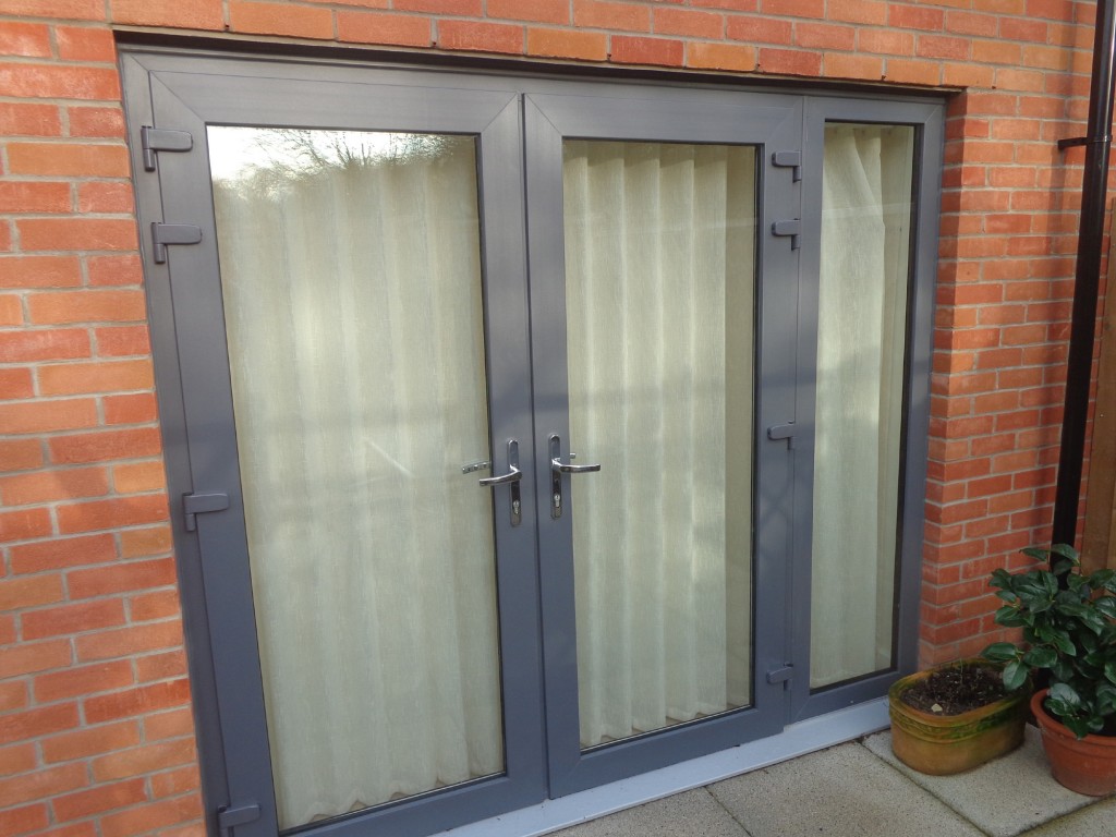
We convinced ourselves that we were cold only because the house would take some time to warm up: the heating had only just been switched on, the house was still drying out, we had left the doors open for two days when moving in, our furniture was cold from 3-months in storage – there was a convincing list of reasons why, in the first few weeks of our residency, the house was not as warm as expected. February moved on to March and then April, the air temperature warmed up, the sun came out on the triple glazed French doors and the house was bathed in warmth.
All was well until November 2015. As the sun disappeared and grey clouds arrived we realised that the cold was returning to the lounge.
Phase 1: The French Doors Need Adjusting
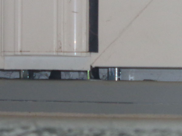
As the first salvo in the war was fired, out came the rugs to avoid cold feet as we ponder our strategy to defeat the problem. I should reveal that the French doors have a level access sill, allowing easy entry for those with a disability but making it harder to see the underside compared with a conventional raised door sill. Our first approach is to feel for draughts around the doors. It’s pretty much game over there and then; that was easy. There are clear gaps in the door seals which are letting in cold air.
A quick call to our housebuilder and their door supplier is on his way to adjust the hinges and align the doors which we are told probably haven’t been adjusted properly during installation. We break out the (French) Champagne to toast our speedy victory.
The door hinges have three axis of adjustment; up/down, left/right and towards/away from the house. So with a quick wave of an hex key the engineer adjusts the doors. For good measure he also adjusts the identical French doors in the kitchen and is on his way.
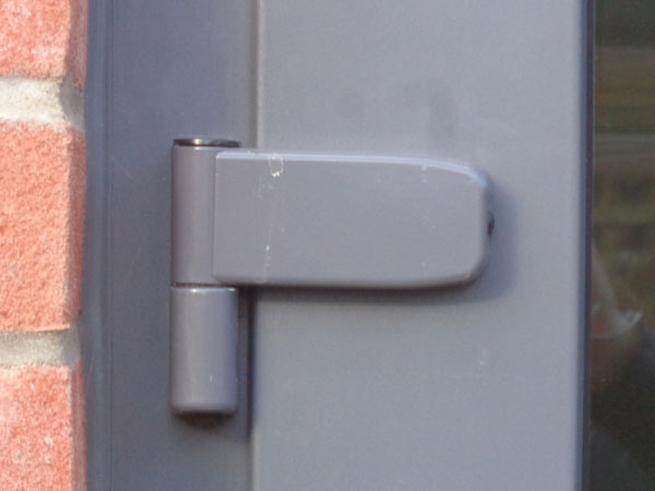
Whilst adjusting the lounge doors we spot a manufacturing defect in the side light which is a fixed panel. This will need replacing as it will only get worse over time but doing it in December is not the best time. We should wait until the spring.
We sit back and wait for the warmth. It never comes. Even worse news, the problem has spread to the kitchen. Having moved our Labrador away from the kitchen doors it feels just as cold on the floor there. Our dog was clearly acting like a canine draught excluder before without us realising. It occurs to us that our two dogs are very effective at measuring temperatures. The Labrador is expert at finding the coolest place in a house whilst our Lurcher can be found at the warmest; normally curled up by the radiator.
Residents 0 French Doors 1
Phase 2: Zut Alors – Maybe It Isn’t The French Doors?
So the door seal has been adjusted but there is still a cold draught. For good measure I tape up the door openings with Sellotape. Not exactly high tech but it does prove that we still get a cold room even if the door is fully sealed. We look to the skies for inspiration and notice an air vent in the ceiling. It’s the outlet to our MVHR system (Mechanical Ventilation Heat Recovery system).
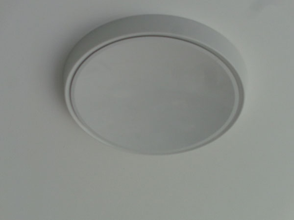
As our home is so air tight we need mechanical help with ventilating it, rather than relying on ventilation losses through the fabric of the building. The system uses a heat exchanger to rescue all the energy in the stale warm air that needs replacing. It then uses this energy to heat fresh air it brings in from outside. It’s great for supplying warm fresh air to the house – it’s one of the big pluses of our new home. See Mechanical Ventilation Heat Recovery Systems (MVHR) Explained.
When we apply our draught detector (a wetted finger) to the outlet of the vent it feels cold. I don’t know how cold exactly as unfortunately the finger is not calibrated with a temperature gauge. We conclude that the MVHR system is pushing out cold air which is bouncing off the doors and making us feel cold. We start the next skirmish in our battle against the cold.
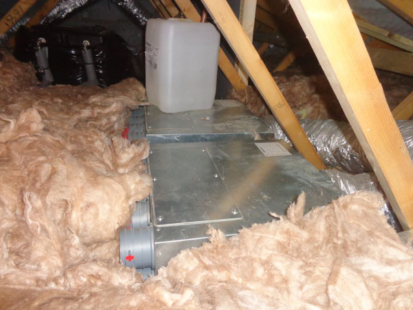
The step ladder is retrieved from the garage to help with a visit to the loft to look at the ducting and distribution boxes for the MVHR system. We see some metal distribution boxes and ducting which together send the heated air round the house. We start wondering why the air distribution boxes are housed in an unheated loft space and why they are not insulated to prevent heat loss?
We also notice red ducting which self-evidently has no insulation round it and goes to our coldest bedroom, also known as my study. I start to realise why the study is a little chillier than I like (and I do like the room cool).
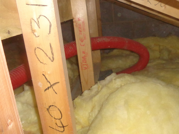
It’s Christmas now and we are not likely to get much sense out of anybody. We spend a few happy hours reading about NHBC standards for our MVHR system. NHBC require the equivalent of 150mm of mineral wool insulation over the MVHR ducting in uninsulated spaces like a loft. There is no specific mention of the air distribution boxes so I put a photo on twitter and ask people whether the boxes should be insulated. I get an answer back that we should insulate them. As a Christmas treat to ourselves we pop down to a DIY store and buy a space blanket to throw over the air distribution boxes. Not a perfect solution but it seems to take the edge off any cold air being blown into the lounge using the wet finger test.
However it still doesn’t feel any warmer in the lounge.
Residents 0 French Doors 2
Phase 3: Reach For The Energy Performance Certificate
With some time on my cold hands over the holiday, I decide to look at our Energy Performance Certificate (EPC) to see if I can understand why our A rated house (rating 98) feels like an igloo. There on page 3 of the EPC it says the annual heating demand for an average household in this property is:
- Space heating – 1,663 kWh
- Water heating – 2,254 kWh
For space heating we have a gas boiler. For water we have solar thermal water heating which operates for the majority of the year and this is supplemented by the gas boiler. There are two of us in the house and in summer the thermal water heating covers upwards of 90% of our needs. In winter it is likely to be close to 20%. I do some basic maths and work out a worst case water heating requirement for gas. Assuming there are 180 days when the solar thermal is not going to help much then using 150 litres of hot water per day and heating the water by 40°C gives an annual requirement for gas to heat water of a generous 1,260 kWh. Add this to the space heating demand and I should be expecting a total gas usage of around 3,000 kWh. We had actually used 6,246 kWh of gas in a little under 11 months with the coldest 40 days of the winter to go. The full year actual gas usage was going to be around 8,000 kWh against an expectation of 3,000 kWh.
Taking out the water heating, our space heating is probably using around 6,700 kWh of gas against an expectation of 1,663 kWh or about four times as much. Not quite what I expected from an EPC A rated house. I email the assessor who carried out the EPC (his email address was helpfully included on the EPC) asking for some advice and get a call from him on the first working day of the New Year. He tells me that the SAP assessment was done on the house design rather than the actual build so does not take into account any differences between “as designed” and “as built” in it’s calculations. Also it is more of a compliance certificate than an accurate prediction of the energy consumption.
The water heating energy requirements in SAP are actually calculated based on an assumed occupancy, which is itself calculated on floor area. SAP does that so the energy performance of different houses can be compared in a standard way. Based on our 101m² floor area, SAP thinks that our house has a theoretical 2.757 occupants rather than the actual 2. So the EPC water heating figure of 2,254 kWh is if anything overstated.
Something isn’t right but I can’t pin it on the French doors. I ponder this before writing an email to the housebuilder’s managing director, highlighting the problems we have with cold and the potential insulation issues with the MVHR system. I ask for his help and suggest his team use some assessment tools such as thermal imaging and air leakage testing to get a handle on the problem.
Residents 0 French Doors 3
Phase 4: Time To Get Some Better Weapons

Dual Laser Non-Contact Infrared Thermometer -50°C to 650°C
Accurate Digital Surface IR Thermometer
At the same time as sending the email to the EPC assessor I began to appreciate that the wet finger test is not a reliable tool for assessing temperature and draughts, particularly if I was talking to professionals.
We have a portable LCD room thermometer but that is useless for measuring surface temperatures so a visit to Amazon enticed me to order a non-contact infrared thermometer. It came within a day or two and allowed me to find the coolest places on the French doors and to reliably compare surface temperatures on all the doors.
When collecting accurate surface temperatures you need to be aware of the different emissivity of different materials but for comparing the same material in different places it is fine. What I wanted to do was compare draughty doors with non draughty doors to see the differences in surface temperatures. That way I would know what to expect when we had fixed the draughty doors. However what puzzled me was I seemed to get similar readings on all our exterior doors. I was getting some data but realised that I needed even more firepower to visualise the problem better.
Residents 1 French Doors 3
Phase 5: Time To Get Some Even Better Weapons
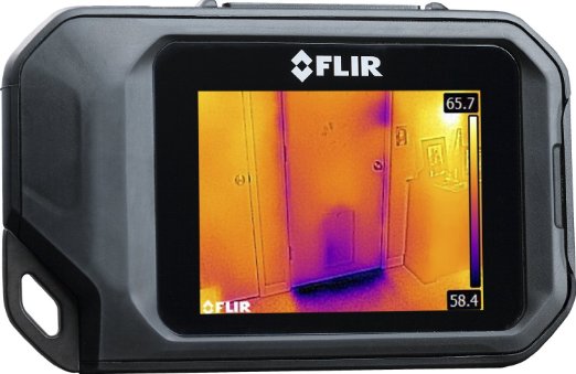
After extended debate and the examination of my bank balance I decided to order a FLIR C2 Thermal Imaging Camera. Ouch, it was £621.49 for the camera and software. There were cheaper options available which could plug into my mobile phone but after bad experiences with trying to juggle mobile phones and attachments I thought a stand alone camera, combined with very good desktop software was the better choice.
Part of the justification for the spend was that, in the back of my mind, I thought I could then convince my mother to replace the 1970’s aluminium patio doors in her home with ones that didn’t have a thermal bridge problem and suffer from heavy condensation.
Residents 2 French Doors 3
Phase 6: Thermal Images Start To Tell A Story
Armed with my new thermal imaging camera I start to photograph things that feel cold. I am not short of subjects. For variety I photograph the dogs. They were certainly warm, especially next to the radiator. After a brief doggy interlude I return to the serious issue of photographing the problematic French doors.
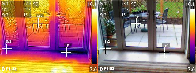
The image above shows a general cold area right across the door threshold / door sill area. The surface temperature at Sp2 is cold at 9.7°C despite the side light area here being a fixed panel with no seal to let air through. Sp3 at 15.4°C shows the benefit of triple glazing. The outside air temperature when the photo was taken was about 4°C and the nominal air temperature in the room was 23°C according to the room thermostat. We don’t normally like it to be more than 20°C but it’s the only way to make the rest of the room habitable. When I measured the air temperature around Sp2 it was 14°C. This dropped to around 10°C if the curtains were closed and the air behind the curtain was not mixed with warmer air from the rest of the room.
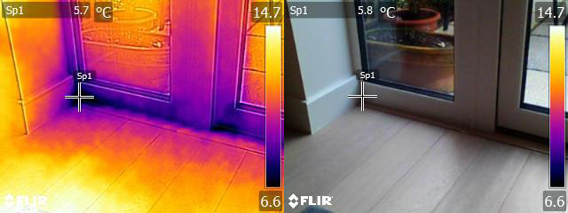
This close up picture shows that the side light where it meets the floor and the wall is at 5.7°C. More like an outside temperature than the surface in a heated room.

The pictures of the French doors in the kitchen told a similar story to the lounge with a cold area around the door threshold. Apologies for the poor illumination of the right hand picture. When taking thermal images you tend to forget that it records both a thermal and a normal image; I didn’t ensure the light levels were sufficient for a standard picture. At least the triple glazed windows are showing a decent temperature of 18°C so we are not losing too much through the glass.
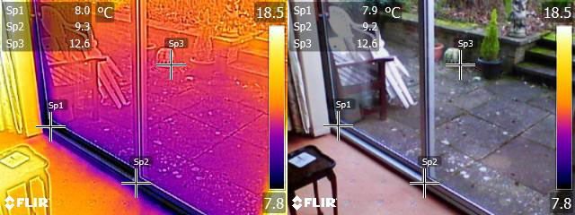
To add to my misery when I visit my mum to take pictures of her 1970s Aluminium sliding patio doors I get temperatures similar to my state of the art triple glazed doors. Not a great argument to convince her to change the sliding doors to something more modern and warmer. The glass in our triple glazing does keep a better temperature but the door threshold temperatures looks worse. I abandon the argument and show mum some thermal images of the dogs instead. She seems to like these. It makes me feel better as well.
Despite the setback against the 1970’s doors I felt we had some good data for a discussion with the housebuilder’s technical and construction team who were calling the next day in response to my email to their managing director.
Residents 3 French Doors 3
Phase 7: Abandoning Hope Of A Solution
The meeting with the housebuilder did not go well. We were told that the manufacturer’s sales representative had confirmed that the MVHR air distribution boxes did not need insulating as they were already insulated inside. Also the manufacturer had been on site during one of the early installations to check that the contractor was installing things correctly. I said I was astounded that the distribution boxes did not need further insulation. The lack of insulation on the ducting itself was met with a shrug.
The French door discussion did not go any better or involve much data analysis. There was some finger wetting and waving around the door seals. I showed my thermal images and explained that the problem existed even when the door seals were taped over. There was scepticism from the housebuilder over the thermal images. They were dismissed with the comment that calibration of a thermal camera was important so my images could not be relied on. I held my tongue but did wonder whether the wet finger being used had been calibrated. The housebuilder would go away to look to see whether the drawings could highlight any problems and to talk to the door supplier. My wife and I started to despair that we would ever break the deadlock.
Residents 3 French Doors 4
Phase 8: A New Hope
After the frustrating meeting it was time for a hot cup of tea and some reflection on what had happened.
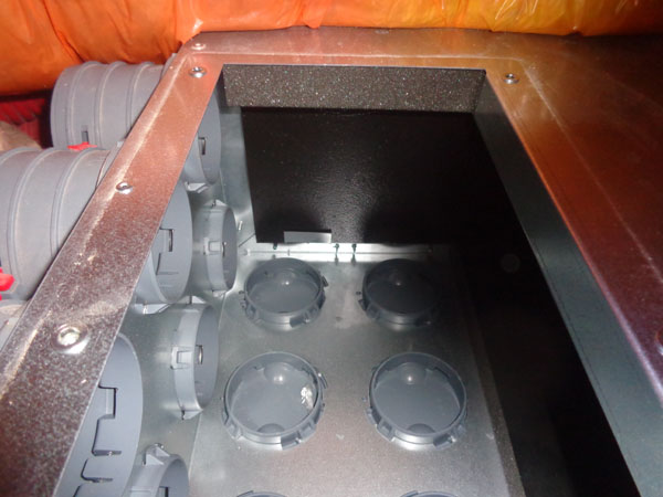
The first place to start seemed to be the MVHR air distribution boxes which the housebuilder had categorically stated did not need further insulation. I braved the loft with a screwdriver to take a look at the boxes. Fortunately the boxes have a maintenance panel, which was removed to reveal a pretty much empty box with some 25mm of soft foam covering much of the inside. The penny began to drop. The soft foam was sound insulation to reduce the potential for noise being transferred between rooms by the MVHR ducting, a known problem with these sorts of systems. It was helpful for acoustics but pretty useless for thermal insulation.
Next morning I struck gold by getting hold of the technical sales manager at the MVHR manufacturer. He confirmed that the air distribution units were sound insulated to reduce unwanted noise but that the unit itself should be thermally insulated as NHBC standards for ducting. I followed this up with an email to the housebuilder, giving them the name of the manufacturer’s technical manager to talk to. I included the photograph of the red ducting to my study which showed the lack of insulation around it which was itself contrary to NHBC standards.
Residents 4 French Doors 4
Phase 9: The Cold Door Problem Expands
Despite the small amount of progress on the MVHR system insulation we could still not pin down the reason for the cold draughts. Having taken thermal images of all the exterior doors in our home we were still not getting any insight into the problem. Looking for problem doors and non problem doors I had found only problem doors. Things were getting worse.
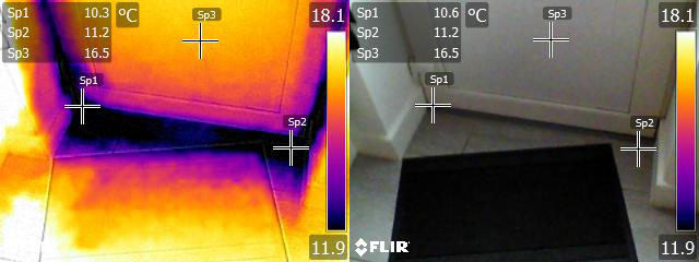
The thermal images of the inward opening utility room door shown above, as well as our front door, had similar characteristics to the outward opening French doors in the lounge and kitchen. All these doors had different designs and used different materials so why would they have the same problem? I had just succeeded in expanding the problem rather than finding the solution.
Residents 4 French Doors 5
Phase 10: The Thermal Bridging Theory Evolves
Whatever the problem was, it appeared to be a consistent one across all the door thresholds. After some consideration thoughts turned to a thermal bridging problem. What if the perimeter insulation was missing, allowing for heat transfer between the outer leaf of the brick wall and the floor slab? Thinking this could be a possible cause I ended up on a section of the Leeds Beckett University website devoted to the Low Carbon Housing Learning Zone section on thermal bridging. This gave food for thought but what evidence did I have or could I get that this was the problem? I started hunting for clues.
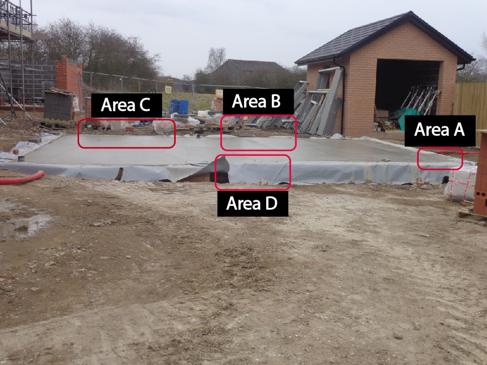
I happened to recall that I had taken some photos of the floor slab of a similar house to our’s during construction. Studying the areas where the doors would go (marked A to D, with C being the lounge French doors) the screed seemed to go upto the outer leaf of brick. It was hardly definitive because the photo was from too far away and the grey DPC, on which the floor screed was laid, covered the outer leaf and it was impossible to say for certain whether insulation was there or not.
In my mind there was certainly a possibility that the perimeter insulation was missing in Area A which was easiest to see and that thermal bridging was the issue. If true this was bad news. I emailed the photo to the housebuilder outlining my theory about missing insulation and potential thermal bridging. I asked them to bring the drawing detail for the floor slab as well as its interface with the door threshold to a scheduled follow up meeting. They planned to bring someone from the door manufacturer as well.
In preparation for the meeting with the housebuilder I visited two neighbours with similar houses, one of whom was reporting similar problems with cold draughts and had requested I take photos. I failed to find a single exterior door in the two properties that did not have the characteristics of our lounge French doors.
Residents 5 French Doors 5
Phase 11: The Sudden Demise Of The Thermal Bridging Theory
Our second meeting with the housebuilder was marginally more productive than the first. There was an acknowledgement that the MVHR air distribution boxes did in fact need insulating; apparently the housebuilder’s contractor had been misled by the manufacturer. There was no explanation why some of the red ducting had not been insulated in the loft.
The housebuilder’s team did not share any drawings of the floor slab but they did bring a photograph of a similar property showing the beam and block floor with perimeter insulation round the outer leaf before the DPC sheet was added. It was difficult to see the precise thickness of insulation from the photo but it was clearly there and I was told it was about 25-35mm wide. This killed my proposed thermal bridging theory.
There was no alternative suggestion for the problem from the housebuilder, but it was agreed that slabs would be removed from the patio outside to allow viewing access to the underside of the level access door sill. The door supplier also agreed to replace our cracked side light and to install a new gasket to replace the door seals in the house. The new door gasket looked like it would expand better when compressed. To replace the cracked side light would involve removing the French doors and reinstating them. I accepted both of these offers but said that in my opinion it would not solve our overall cold draught problem so it would need to be done at the same time as the patio slab removal with both the door and housebuilder teams on site together.
Some of the phrases used by the housebuilder during this dialogue were not ones that those in a sales or customer service environment would normally consider using with an unhappy customer. I will leave it at that.
Residents 5 French Doors 6
Phase 12: Looking At Things Differently
After the housebuilder meeting I was annoyed; annoyed that we seemed to be making such little progress on identifying the problem, let alone finding a solution. I contacted Leeds Beckett University and gained the help of an expert from their Low Carbon Learning Zone. They gave me some very helpful suggestions on what to look for. It made me realise that if only I could see what was happening under the door sill things may be clearer; however that was impossible without removing the slabs as the level access door sill had no space underneath to get any sort of view. I would have to wait for the housebuilder.

Although actually there was a slight gap underneath the lounge French door sill of about 9 or 10mm; tiny but if I could only get to it somehow. Then it dawned on me that a number of different professions do have the problem of trying to view difficult to access areas: be it in engineering or building inspection. Using a borescope or endoscope could help. I found the perfect tool on Amazon, an 8.5mm 2 Megapixel video camera with LED illumination lights and 5 metres of cable with a USB connection to connect to a laptop. At £20.50 it had to be worth a shot.
A couple of days later I was kneeling by the French doors with the endoscope and a laptop looking at video images of the underside of the door sill. The video images confirmed there was a problem. There were large parts of the underside of the door sill that had a 10mm gap under it, with no seal between the sill and the brickwork. This would account for why our lounge felt as cold as it did; outside air and potentially water was getting under the door sill, bypassing the door itself and the DPC. It could also explain why all our exterior doors were affected.
The best thing about this was that there was a simple way of remedying the problem; take up the slabs under the doors sills, seal properly and reinstate the paving slabs; far easier than removing doors and having to make good internal decoration.
I uploaded the original video to YouTube so I could share it with the housebuilder and the door company. It’s not going to make a “Popular on YouTube” slot but it has served its purpose.
You can view an “edited highlights” version of the video above, shortened to 50 seconds running time.
The video starts on the left side of the French doors and moves about 60cm to the right under the door sill in a series of jerky movements. I won’t make a professional endoscope operator but hopefully you can make out the 10mm gap I am talking about. I am just pleased the image recorded the right way up as it’s hard to tell the camera orientation. The camera takes a couple of seconds to get the light levels right each time it is moved and it has a fixed focus of about 8cm. The gunk under the sill is material that has been blown there by the wind; there are probably a few spiders lurking there too. The lack of a seal can be seen on the video at 23 seconds and at 30 seconds you can see a bit of the DPC on the left of the picture.
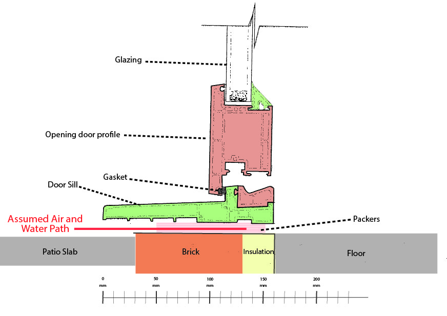
I thought it was time to try and visualise what was happening under the door sill as it connected with the brickwork, perimeter insulation and floor screed so I produced an approximate drawing of what I imagined was there. My thinking is that the sill is raised on packers which are spaced approx every metre along the length of the sill. So there will be places where air and water could get into the house unless stopped by any expanding foam the door installer has put on the inside (not shown). Since I had no drawings from the housebuilder I was hoping to pick the brains of the door company when they come to replace the side light. They will no doubt put me right on what the door actually looks like.
Residents 6 French Doors 6
What Next?
Well that brings us up to date so far. We know far more but are still cold. The original endoscope video was uploaded on the 1st February and we are now waiting for a new side light to be available before the fun and games start on our lounge French doors. We are also expecting some additional insulation for the MVHR components in the loft. I can’t claim we have snatched victory yet so let’s just say that time is running out for the French doors to fight back again. I will provide an update once we have seen some progress from the housebuilder and door supplier.
Update 2 March 2016: See Draught Problems: The Battle With The French Doors Part 2
A useful article, but I get feeling that the door company didn’t come up with any improvements. Like you I examined my house with a thermal camera, many years after we effectively rebuilt the house. This straight away showed a problem with the french doors, almost all the way round. One cause was simple, in that I could see the outside at one angle, when I looked at the top of the door. So simply an incorrectly made door, but who would check it. The firm is a long running well known local company. The bottom was improved by replacing seal and gluing on extra pieces, but It realy improved with a old fashioned draft exluder fabric cylinder.
Reading further I have realised that the correct fitting of windows for energy saving is not that common. A problem with the british construction industry who have not been trained in this issue
how does one adjust the patio door in a skew motion? My doors are slightly skewed. Not square. Image a A4 Printing paper paper not straight. I want to skew only one corner, is this possible or if yo can point me to some printable material with guides. thanks
Hi William,
If your doors are mounted using 3D-hinges then these usually have circa 5mm adjustment (+/- 2.5mm) on the height and side movement and circa 4mm adjustment (+/- 2mm) on the compression (moving the door further/close to adjust how much the door compresses the seal). By adjustments using an allen key you can compensate for a slightly skewed door but if the door or frame are skewed or under/over size by more than a couple of mm then one of them would need to be remade to avoid having a gap. I’ve not come across a printed guide to the procedure but when watching installers they seem to adjust the height of all hinges first then the side and finally the compression. The problem with having a skewed door to start is that with slight expansion and contraction (during summer/winter cycle) then there is a risk the door will catch at some stage.
Hope this helps.
Kind regards
Jon